
Every product designer has to deal with the issue of electromagnetic compatibility (EMC) or electromagnetic interference (EMI) on a daily basis – especially when using frequency-determining components such as quartz oscillators. The ICs installed into quartz oscillators generate steep, sharp-edged flanks and produce strong harmonic overtones. Spread-spectrum oscillators are one solution to this, but there are many applications where they cannot be used. With a centre spread of ±0.5 %, for example, the output frequency is modulated within a range of fout ±0.5 %. Given a frequency of 33.333 or 66.666 MHz, a frequency modulation of ±0.5 % would imply a frequency modulation range of 33.333 MHz ±166.665 kHz or 66.666 MHz ±333.330 kHz – too great for precise clocking. These applications typically only allow ±50 ppm, or in other words a factor of 100 less. A frequency stability of ±50 ppm equates to a tolerance of ±1.66665 kHz at 33.333 MHz, or a tolerance of ±3.3333 kHz at 66.666 MHz. In such cases, the developer has so far had to take very expensive measures to reduce EMC – EMI. This is no longer necessary. Based on innovative IC technology – next generation clocking – Petermann-Technik from Landsberg am Lech offers a highly diverse range of SMD silicon clock oscillators featuring a SoftLevel output signal. SoftLevel technology is a programmable output signal in which the harmonic overtones of an LVCMOS output signal can be significantly reduced by prolonging rise time (trise) and fall time (tfall). SoftLevel technology allows precise adjustment of the output signal to the respective customer requirements.

Figure 1: Period t of an LVCMOS output signal with trise and tfall between 20 % and 80 %.tfall
What the SoftLevel function does
Figure 1 shows the period t of an LVCMOS output signal with trise and tfall between 20 % and 80 %. Figure 2 shows the flank contour of a normal LVCMOS square-wave signal (red line) compared to the SoftLevel LVCMOS output signal (blue line) at a supply voltage of +3.3 VDC. The graph clearly shows how the SoftLevel function rounds the edges of the square wave (producing a shark-fin-like shape) and thus significantly reduces harmonic overtones. Figure 3 shows the EMC – EMI attenuation (odd harmonic overtones) in relation to the period t of the output signal. trise and tfall are expressed in proportion to the period t of the clock signal.
trise and tfall can be prolonged in the range from 0.05 to 0.45 (5 % to 45 %) of t. If trise and tfall are prolonged by 5 % compared to the base signal, then the signal shape comes very close to the original square-wave signal. At a prolongation of up to 45 %, the shape of the output signal increasingly resembles a shark’s fin, and the EMC – EMI attenuation is greater than ‑60 dB at the 11th harmonic overtone. An enormous value for such a simple adjustment of trise and tfall.
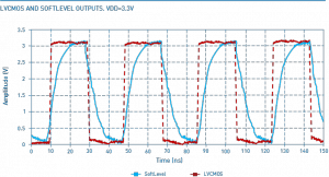
Figure 2: Flank contour of a normal LVCMOS square-wave signal (red line) compared to a SoftLevel LVCMOS output signal (blue line) with rounded edges.
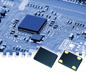
What does the SoftLevel function cost the developer? Nothing, since the SoftLevel function is a standard feature of SMD silicon clock oscillators of the LPO, LPOP, HTLPO, WTLPO, UPO, HTLPO-AUT and WTLPO-AUT series. (AUT = Automotive as defined in AEC-Q100). These oscillator series are furthermore available in standard housings dimensioned at 7 mm x 5 mm, 5 mm x 3.2 mm, 3.2 mm x 2.5 mm, 2.5 mm x 2.0 mm and 2.0 mm x 1.6 mm, and can thus be placed on existing PCB layouts as an immediate and direct replacement for quartz oscillators. So that In-House Engineering at PETERMANN-TECHNIK can advise the customer optimally and program a product according to the specific needs of the application, the developer must say exactly what trise/tfall times he can accept in his application. It is this programming – prolongation of trise/tfall – that achieves the harmonic overtone attenuation. In the SMD silicon clock oscillator circuit design, the specialists of Petermann-Technik recommend using a 0.1 μF decoupling capacitor between the supply voltage and ground pins. This considerably minimises the influences of the supply voltage.
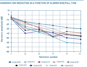
Figure 3: EMC – EMI reduction in relation to the longer period.
Other advantages of SMD silicon clock oscillators
SMD silicon clock oscillators from the above series are also available for a supply voltage range of 2.25 to 3.63 VDC. The oscillators can be driven by any supply voltage within this VDD range (e.g. 2.5 VDC ±10 %, 2.8 VDC ±10 %, 3.0 VDC ±10 % or 3.3 VDC ±10 %). Thus, the product developer only has to qualify one oscillator for four classical supply voltages. This standard feature spares the developer a lot of money for component qualification, and the supply chain manager a lot of money for the procurement, management and storage of significantly fewer components. Components purchased in greater bulk quantities come at a lower price. And, of course, the SoftLevel function can also be employed in the VDD range of 2.25 to 3.63 VDC as a standard feature. As another standard feature, SMD silicon clock oscillators have very tight frequency tolerances, for example ±20 ppm @ ‑40/85 °C, ±30 ppm @ ‑40/105 °C and ±50 ppm @ ‑40/125 °C. Naturally, AEC-Q100-compatible oscillators (HTLPO-AUT and WTLPO-AUT) are also available with all of the features described above.
SoftLevel function improves EMC – EMI characteristics
The EMC – EMI characteristics of SMD silicon clock oscillators can be significantly improved by simply adjusting trise and tfall of the output signal, at no cost, using the SoftLevel function, meaning the developer no longer has to take expensive measures to improve the EMC – EMI performance of his application. SMD silicon clock oscillators can be placed directly on existing PCB layouts. Furthermore, given a VDD range of 2.25 to 3.63 VDC and very tight standard frequency tolerances, a lot of money can be saved for component qualification, procurement, management and storage.
More information under:
Silicon oszillators product overview
Technical enquiries:
Telephone: 0 81 91 / 30 53 95
Email: info@petermann-technik.de